FMP type controller
Rating excitation
The FMP is a contactless controller used for C&B motors and small capacity clutches/brakes. The contactless power transistor circuit used for clutch/break switching is very reliable and the discharge circuit uses a capacitor technique to improve the cut off characteristics, improving precision and high frequency control.
FMP-10DA
Features
• With the adoption of a timing circuit, the interference between the clutch and the brake is eliminated and we obtain stable, efficient operation.
• The equipment is very compact due to control circuit integration and assembly of all parts (except the transformer) on printed circuit board.
• Simply connect the AC input, clutch/break and external signal and you are ready to operate.
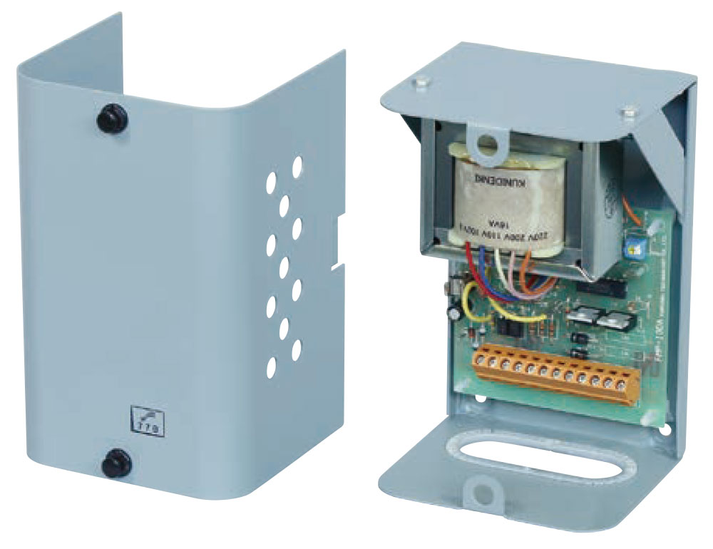
Dimensional outline drawing
T: Transformer
TI: Terminal block
EF: Fuse
RH60: Volume for time lag adjustment
ABC. Px. Py. Pz: Input signal switching pin
PC: Printed circuit board
Specifications
| Model | FMP-10DA | |
|---|---|---|
| Input voltage AC V | 100/110・200/220 | |
| Fuse capacity A | 1 | |
| Output voltage DC V | 24 | |
| Capacity W | 10 | |
| Rating | Continuous | |
| Adjustment (Volume variable) | Time lag (ms) | 0-45 (20 at shipping) |
| Circuit direction |
IC contactless circuit |
|
| Structure | Steel plate, wall mounting, protective type | |
| Weight kg | 1.5 | |
| Painting color | Munsell 7.5BG6/1.5 | |
| Main applicable electromagnetic clutch/brake | C&B pack, MP4-5, BO/BB2-5 | |
Don't connect varistor for discharge circuit
External connection diagram
1. PS terminal is for switching CL/MB through the external power source. See the operation manual for details.
2. Only a current of several milliamps can be used as the external source, so please use an appropriate input.
Memo
- The lifespan is nearly permanent due to the adoption of a contactless mechanism.
- By simply changing pins (A,B,C), it can be used either for 2 signals or a single signal. (Factory settings indicate 2 signals).
-
It achieves stable operation even under high frequency use due to a wide time lag adjustment range. For both clutches/brakes, the time lag adjustment is done by RH60, and by turning it clockwise, you can increase the time lag (It is set to be 20ms at the factory).
CAD
Information obtained from CAD data should be treated as reference only, except for the dimensions shown.
Please note that bolt and tap positions may change.
All information is subject to change without notice due to quality improvement or modification.