Vibrating Feeders
Various models with flexible feeding capacity from fine powders to lumps
As powder/pellets processing equipment becomes more efficient and precise, there is a demand for high-performance feeders that can not only feed and cut materials, but also control the flow rate to the subsequent process quickly and extensively.
In order to meet the demands of industries that handle such powders and granules, Sinfonia Technology has manufactured vibration feeders that apply our unique vibration technology, which have already gained a high level of trust from various fields. Sinfonia Technology's vibration feeders, born from our many years of vibration technology and extensive manufacturing experience, promote process streamlining and productivity improvement.
Sinfonia Technology's vibration feeders, which utilize the vibration transport phenomenon, are available in three models: the electromagnetic feeder, the linear feeder, and the rubber spring feeder, which utilizes the vibration caused by the rotation of unbalanced weights.
When selecting a vibrating feeder, it is necessary to fully consider the shape, characteristics, and feed rate of the material to be handled, as well as installation conditions, operating conditions, hopper shape, factory environment, and other factors. Sinfonia Technology has a long track record of delivering vibrating feeders to powder and granular processing plants and has a wide variety of models that are manufactured based on strict tests, enabling us to offer the optimum vibrating feeder for any application or purpose, regardless of the conditions of use.
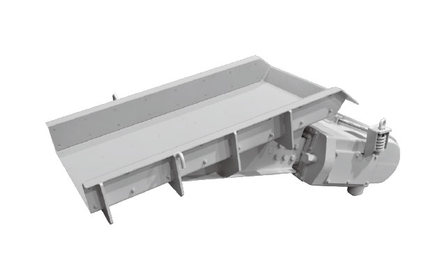
CF/F Type Electromagnetic Feeders
Multipurpose type from fine powder to large lumps
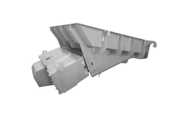
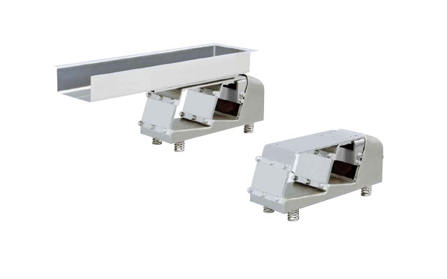
RFH Type Rubber Spring Feeders
High-capacity type for high-speed and large-volume
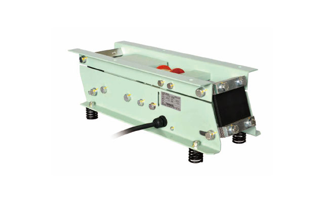
Water-resistant Electromagnetic Feeder
Whole Body is Washable, and Suitable for Manufacturing Lines of Food and Medicine.
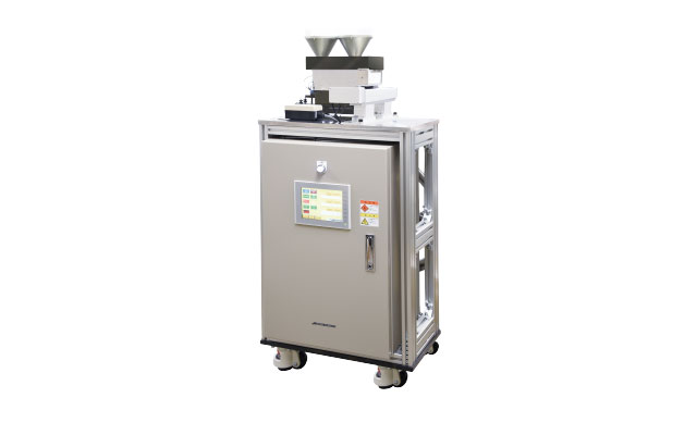
Micro Fixed-Quantity Feeder
Realizes continuous feeding and discharging with micro-quantitative feeding of high-functional materials
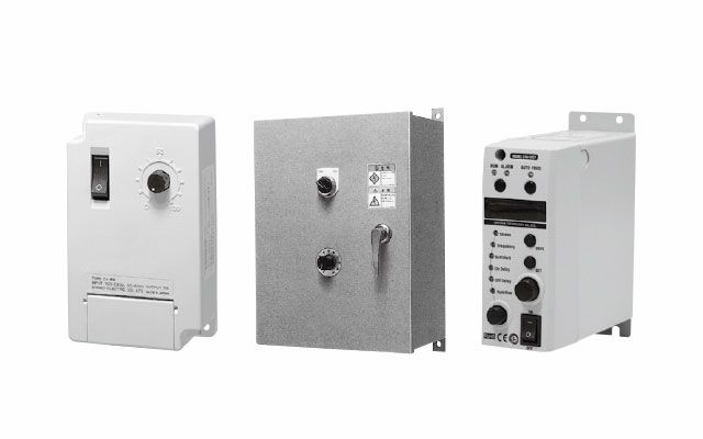
Controller
Small Type Feeders
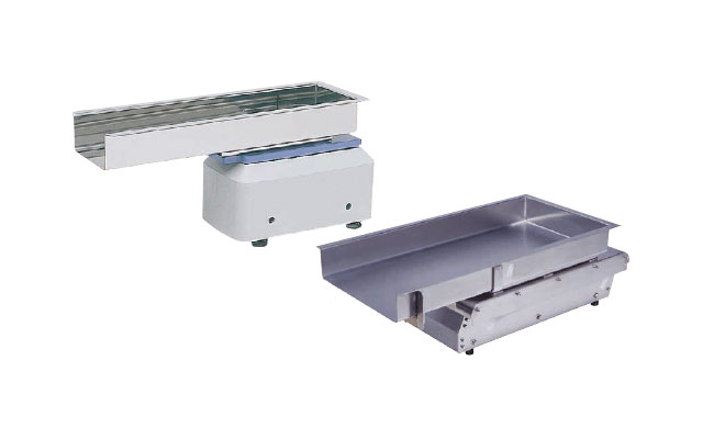
CF Type Small Vibrating Equipment
New-type electromagnetic feeders that are easier to use
CF-1
CF-2
CF-3
CF-4
WCF Type Water-resistant Electromagnetic Feeder
Providing Safe Food by Preventing Contamination
Washable compact feeder
WCF-2A
WCF-3
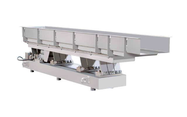
LF Type Linear Feeders
Suitable for Linear conveyance of various fine powders
LF-30/40
Features
- Easy Automatic Feed control
Easy feeding adjustment by turning the feeding control knob. The feeding volume of vibrating feeders can be easily and automatically controlled through combination of a weighing machine, flow meter, thermometer or motor load, and by detecting fluctuations thereof. Especially by being combined with the weighing machine, the feeder is frequently utilized as a hopper scale for mixing raw materials. - Wide range of handling materials
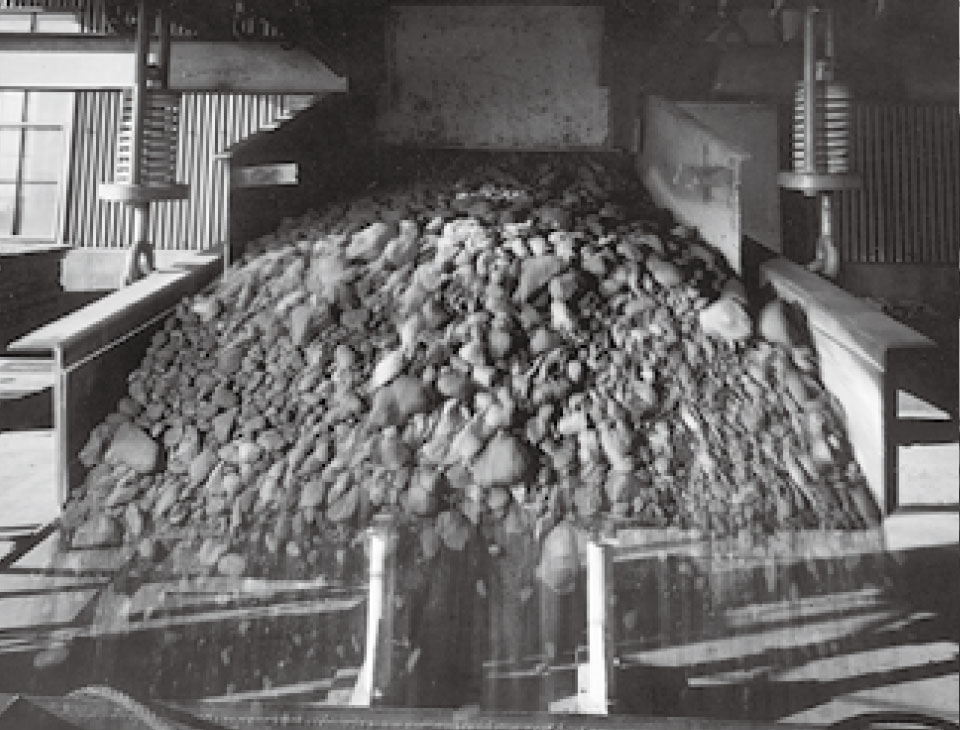
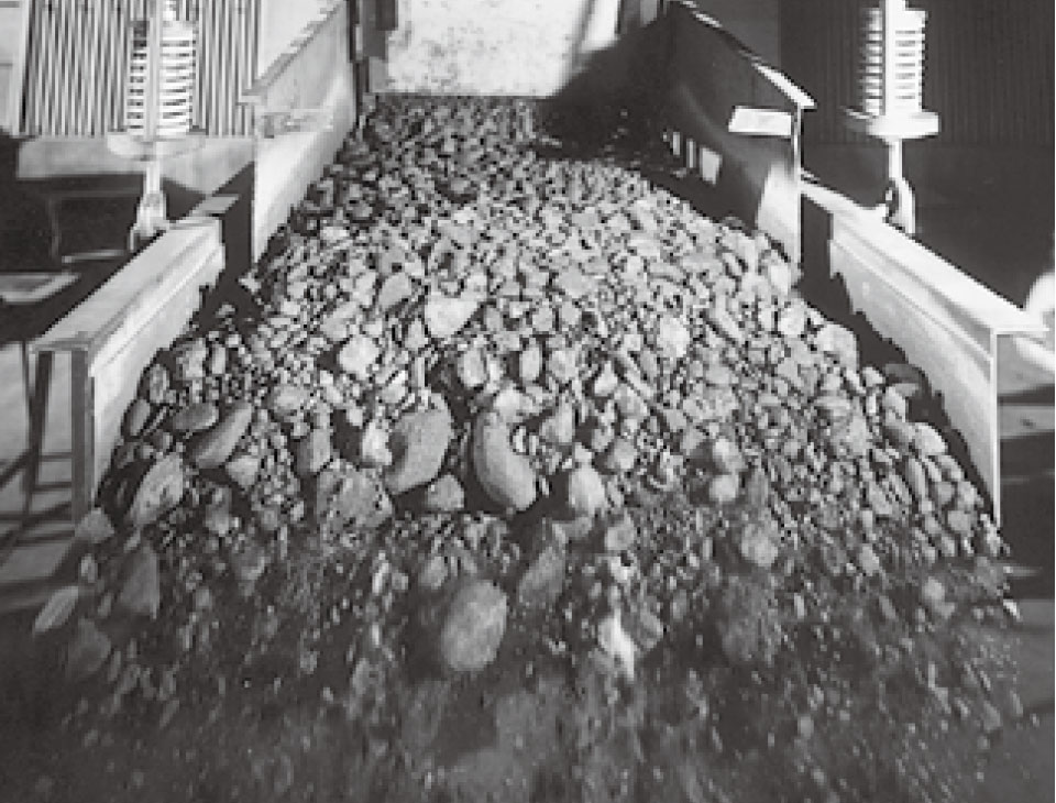
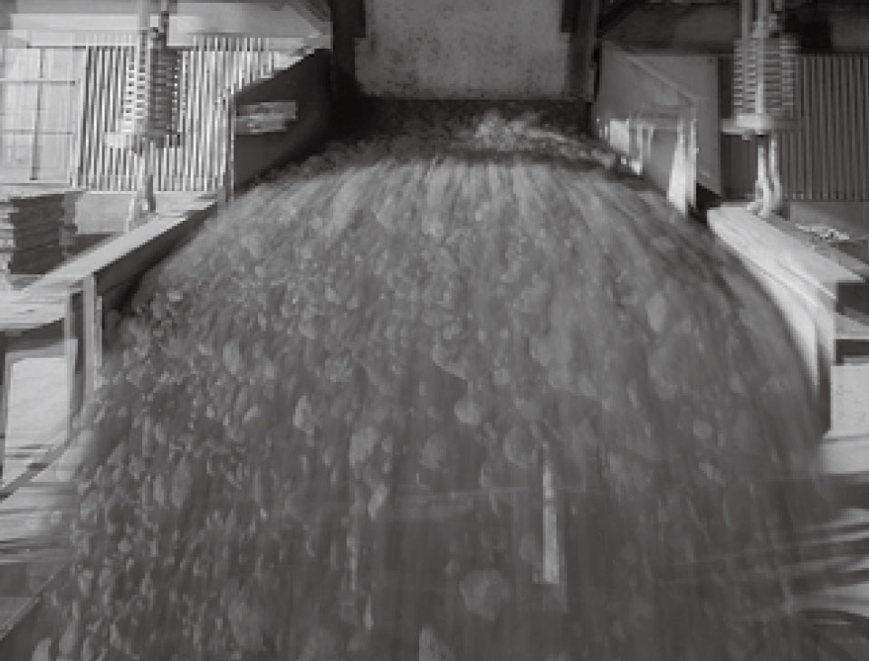
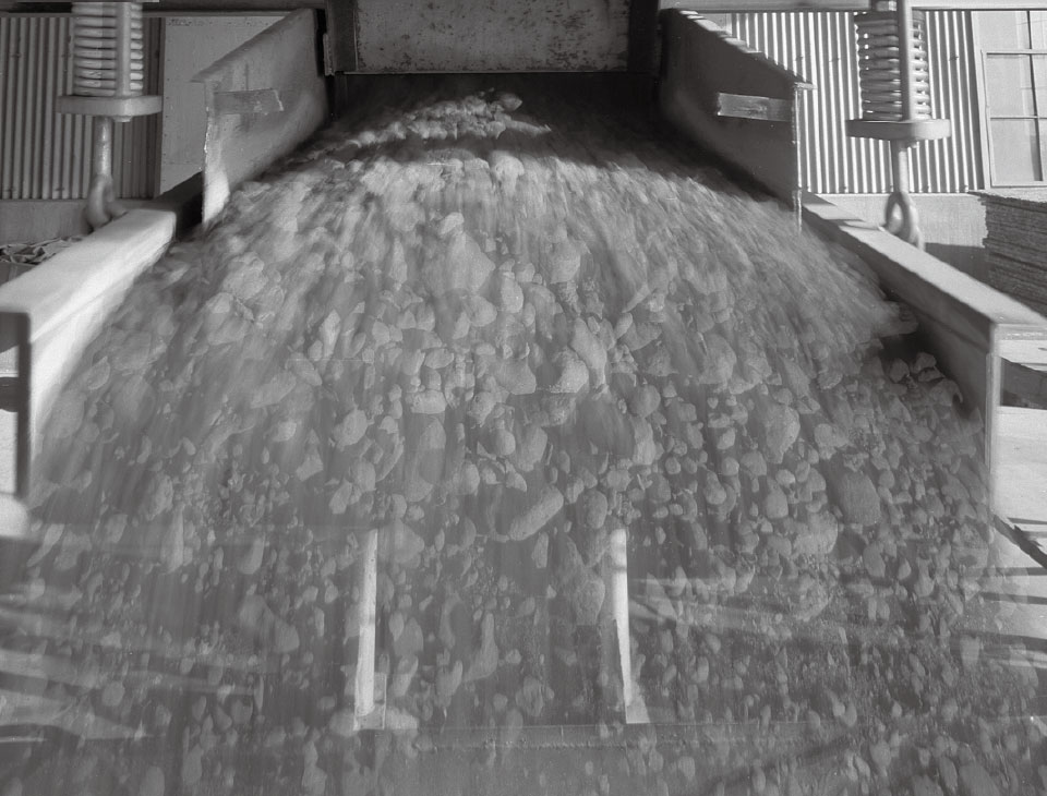
Vibrating feeder can process a wide range of materials and efficiently convey a variety of materials from fine to massive bodies. The feeder is also suitable for high temperature, high abrasion material feeding. A large-sized feeder having a capacity of conveying iron ore at a rate of 6,100 tons per hour is also available. - Low running cost
Vibrating feeder consume very small electric power by means of utilizing the resonance phenomenon, which is extremely economical. Vibrating feeder’s easy structure saves maintenance and inspection time. Furthermore, no friction exists between a trough surface and conveyed material, which relates to trough long life span. As a result, maintenance cost of the vibrating feeder will be dramatically reduced, and cut back cost. - Suitable for specialized operation
A number of feeding modifications are available; dust or gas tight troughs and covers; special inlets and outlets, many more. And also, a waterproof type and a heatproof type are also available.
Model List
| Model | Drive mechanism | Power supply | Suitable materials for handling |
|---|---|---|---|
| CF/F Type Electromagnetic Feeders |
Resonance type consisting of electromagnet and leaf spring |
Commercial single phase | Wide range of materials from fine to massive material |
| RFH Type Rubber Spring Feeders |
Resonance type consisting of 3-phase induction motor, rubber spring and unbalanced weight | Commercial 3-phase | Pulverulent, granular and massive materials |
| Model | Maximum Amplitude (mm) |
Vibrations per minute, 50/60Hz | Max feeding capacity (T/Hr) (*1) |
Adjustment of feeding capacity | Starting | Stopping | Applicability to weighing machine | Maintenance | |
|---|---|---|---|---|---|---|---|---|---|
| (Electrical) | (Mechanical) | ||||||||
| CF/F Type Electromagnetic Feeders |
1.8 | 3000/3600 | 1250 | (*2) 30~100% |
Opening ratio of gate Angle of inclination |
Instantaneous | Instantaneous |
Excellent |
Easy |
| RFH Type Rubber Spring Feeders |
7 | 1000~1150 | 5000 | 40~100% | Opening ratio of gate Angle of inclination Unbalanced weight |
Easy | Possible instantaneously | Good | Easy |
1.The max.feeding capacities apply to standard flat-bottm open type with skirts when bulk density of sand is 1.6, though angle is 10° and frequency is 60 Hz.
2. About F Type, feeding capacity can be freely adjusted between 0-100% by adjusting opening ratio of gate.
Conveying capacity for individual materials
Calculating conveying capacity for individual materials
F type Feeders feature a special feeding system in which the trough vibrates obliquely to feed materials.
The following equation gives the feeding capacity depending on the material to be handled when F type Feeder equipped with the uncovered flat bottom standard trough is used.
Feeding capacity shows for standard sand (bulk density: 1.6, moisture content: 1%, Particle size: 20mesh), and can be obtained from Table 1
γ: Bulk density of material
C1: Conversion factor for particle size (Fig.1)
C2: Conversion factor for moisture content (Fig.2)
C3: Conversion factor for trough inclination (Fig.3)

Materials having excessive stickiness, nature of flashing, and a large bulk density are excepted from this equation.
Movement diagram of material
Ratio between particle size of material and feeding efficiency
Ratio between moisture content of material and feeding efficiency
A=materials that do not dissolve in water (sand, coal, coke, etc.)
B=materials with affinity for water (salt, clat, plaster, etc.)
Ratio between trough inclination and feeding efficiency
Max. feeding capacity of F type Feeder/Table 1
| Mode | Max. feeding capacity (T/Hr) |
Trough size width×length (mm) |
Voltage (V) | Frequency (Hz) | Vibration per min. |
|---|---|---|---|---|---|
| CF-1 | 2 | 100×380 | 100/200 | 50~70 | 3000~4200 |
| CF-2 | 5 | 120×550 | 100/200 | 50~70 | 3000~4200 |
| CF-3 | 8 | 150×610 | 200 | 50~70 | 3000~4200 |
| CF-4 | 25 | 380×800 | 200 | 45~60 | 2700~3600 |
| F-152BDT | 10 | 200×610 | 200/220 | 50/60 | 3000/3600 |
| F-212BDT | 35 | 310×762 | 200/220 | 50/60 | 3000/3600 |
| F-22BDT | 50 | 356×914 | 200/220 | 50/60 | 3000/3600 |
| FH-22BDT | 65 | 458×914 | 200/220 | 50/60 | 3000/3600 |
| F-33BDT | 100 | 558×1067 | 200/220 | 50/60 | 3000/3600 |
| FH-33BDT | 130 | 610×1067 | 200/220 | 50/60 | 3000/3600 |
| F-44BDT | 220 | 762×1219 | 200/220 | 50/60 | 3000/3600 |
| F-45BDT | 330 | 914×1524 | 200/220 | 50/60 | 3000/3600 |
| FH-45BDT | 440 | 1219×1524 | 200/220 | 50/60 | 3000/3600 |
| F-55BDT | 600 | 1372×1524 | 200/220 | 50/60 | 3000/3600 |
| F-66BDT | 800 | 1524×1829 | 200/220 | 50/60 | 3000/3600 |
| F-88BDT | 1250 | 1829×1829 | 200/220 | 50/60 | 3000/3600 |
The max. feeding capacities apply to standard flat-bottm open type with skirts when bulk density of sand is 1.6, though angle is 10∞ (horizontal for modeles F00B~11B) and voltage is 80Hz.
Feeding Capacity for Respective Materials (on 60Hz T/Hr)
| Model | Depth of material (mm) |
Trough inclination downward |
Materials | ||||||||
|---|---|---|---|---|---|---|---|---|---|---|---|
| Quick lime |
Iron ore |
Lime stone |
Coke | Sintered ore |
Chemical fertilizer |
Resin pellet |
Sugar | Granular foods |
|||
| F-212BDT | 100 | 6° | 17 | 30 | 22 | 9 | 25 | 16 | 8 | 15 | 7 |
| 10° | 18 | 33 | 24 | 10 | 27 | 17 | 9 | 16 | 8 | ||
| F-22BDT | 120 | 6° | 25 | 42 | 32 | 13 | 35 | 22 | 12 | 20 | 10 |
| 10° | 26 | 45 | 34 | 14 | 38 | 23 | 13 | 21 | 11 | ||
| FH-22BDT | 130 | 6° | 31 | 52 | 40 | 17 | 43 | 28 | 15 | 26 | 13 |
| 10° | 33 | 56 | 43 | 18 | 47 | 30 | 16 | 28 | 14 | ||
| F-33BDT | 180 | 6° | 53 | 89 | 69 | 28 | 76 | 48 |
25 |
44 | 21 |
| 10° | 56 | 96 | 73 | 30 |
81 |
51 |
27 |
47 |
23 | ||
| FH-33BDT | 200 | 6° | 65 | 108 | 84 | 35 |
93 |
59 | 31 | 54 |
27 |
| 10° | 68 | 118 | 89 | 37 | 98 | 62 | 33 | 57 | 29 | ||
| F-44BDT | 250 | 6° |
103 |
173 | 133 | 56 | 147 | 95 | 50 | 86 | 44 |
| 10° | 108 | 188 | 143 | 58 | 157 | 100 | 52 | 92 | 46 | ||
| F-45BDT | 320 | 6° |
146 |
244 | 188 | 79 | 208 | 136 | 71 | 122 | 62 |
| 10° | 153 | 264 | 201 | 83 | 222 | 142 | 75 | 130 | 65 | ||
| FH-45BDT | 360 | 6° |
191 |
319 |
247 |
103 | 272 | 175 | 93 | 159 | 80 |
| 10° | 200 | 346 | 263 | 108 | 289 | 185 | 97 | 170 | 84 | ||
| Bulk density (g/cm3) | 1.0~1.2 | 2.1~2.2 | 1.4~1.6 | 0.5 | 1.6~2.0 | 0.9 | 0.45 | 0.8 | 0.4 | ||
| Moisture content (%) | 0 | 0~10 | 0~10 | 0~5 | 0~5 | 1~4 | 0 | 0.2 | 5~15 | ||
| Particle size (mm) | 2~30 | 5~50 | 2~30 | 15~75 | 5~50 | 1.5~4 | 2~5 | 0.3~1 | 0.5~3 | ||
The feeding capacities apply to standard coverd type when voltage is 50 Hz, and adjusted to 1.2 times when voltage is 60Hz.
Suspend Method
Wire
In case of long suspending distance
Turn Buckle
Adjustable of little extent
Suspending Hook
In case of short suspension distance
Special Suspension Tools
When the feeder is especially large and turn buckles & suspension hooks are not available in the market.

Never tighten the bracket as shown below.
Hopper Mounting Example
The shape of the hopper is an important factor which determines the supply capacity of the feeder. The required supply capacity may not be able to be obtained depending on the hopper shape. In designing an ideal hopper economical and essintial to full feeder performance, it is necessary to take the following into account.
The rear wall angle α shown in the figure should be 60 degrees or more to ensure smooth flow of material. The front wall angIe β should be 5 degrees smaller than the angle α.
The hopper tends to devolop a bridge at the throat indicated by the letter, T, so the part T should meet the following conditions.
・ 2.5 times the largest massive body if material is not uniform in particle size.
・ 4 times the largest massive body if material is relativery uniform in particle size.
The gate opening B should be at least 2 times the largest massive body, and increase in direct proportion to the required capacity. The standard gate opening rate B is 1.2 to 1.5 times the material layer thickness d, which can be calcuIated by the following equation.
The hopper opening rate W should be 2.5 times the largest massive body if material is not uniform in particle size, or 5 times the largest massive body if material is relatively uniform in particle size.