RFH Type Rubber Spring Feeders
High-capacity type for high-speed and large-volume
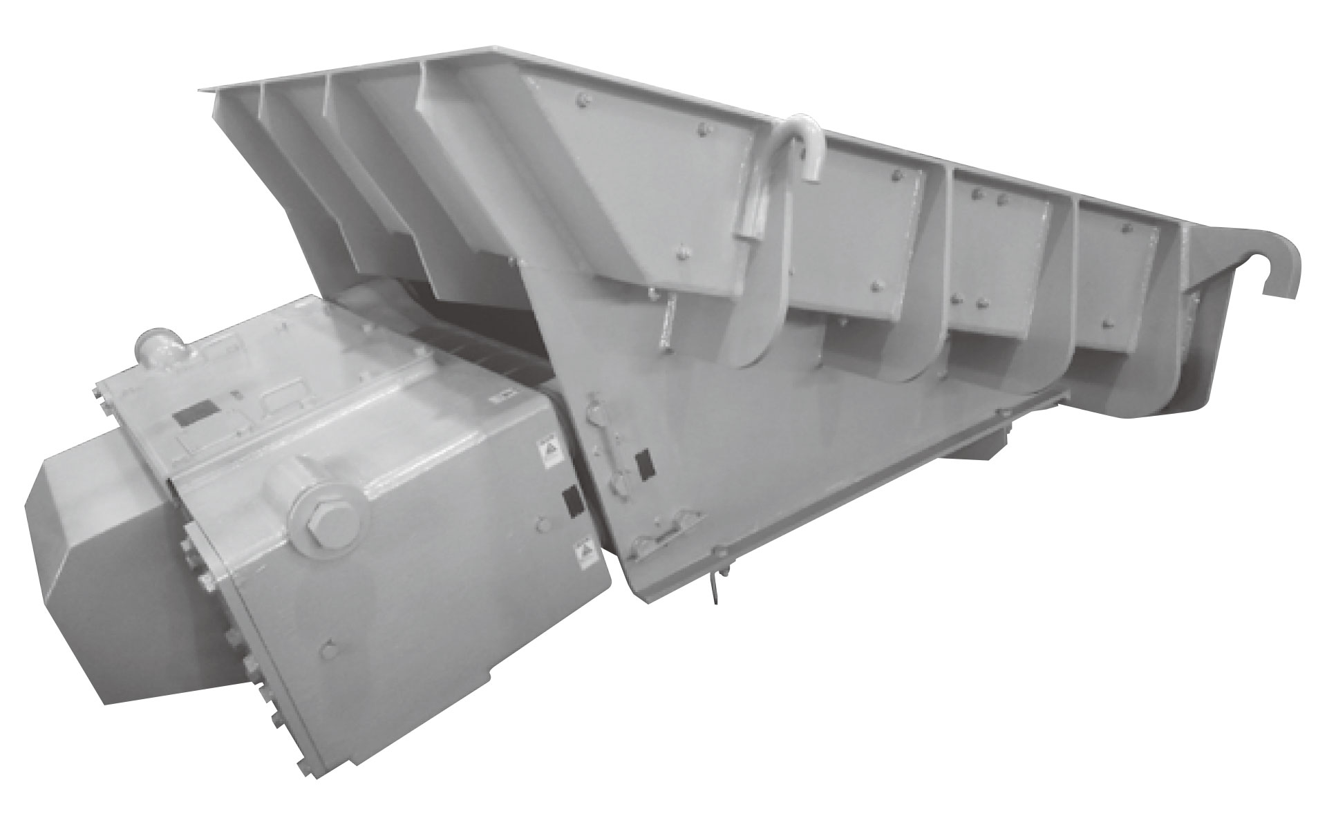
This Rubber Spring Feeders are vibrating feeders in which strong vibration generated by rotation of unbalanced weights is effectively combined with rubber springs. Due to the use of resonance vibration, high efficiency can be obtained and only a small amount of drive power is required.
As the feeding rate is easily adjusted during feeder operation and instant interruption of the flow of material is possible, this equipment also can be used as a weighing feeder.
Suspended
Base mounted
Operating Principle
The structure consists of a trough that carries the material, a drive unit that generates the vibration, and a resonant rubber spring that connects them. The elliptical vibration generated by the rotation of the unbalanced weight in the drive unit has the same effect as linear vibration on the material on the trough. Therefore, a large amount of powder, grain, or bulk material can be speedily cut out and fed.
Structural Diagram
Both suspension type and floor-mounted type are installable.
The trough and the drive unit are hold by suspension device (if you use a suspension type) or supporting device (if you use a floor mounted type).
Specifications
Standard Specifications
| Model | Feeding capacity (T/Hr) |
Motor (kW) | Trough size width×length (mm) |
Gross weight (kg) | Applicable controller |
||
|---|---|---|---|---|---|---|---|
| Iron ore*1 | Sand*2 | Coal*3 | |||||
| RFH-10A | 150 | 130 | 60 | 0.2 | 450×800 | 100 | CA-2FR |
| RFH-20A | 250 | 210 | 100 | 0.4 | 600×1000 | 200 | CA-4FR |
| RFH-45A | 450 | 370 | 180 | 0.75 | 800×1200 | 400 | CA-7FR |
| RFH-60A | 650 | 530 | 260 | 1.5 | 900×1500 | 600 | CA-15FR |
| RFH-85B | 800 | 680 | 350 | 2.2 | 1100×1500 | 800 | CA-22FR |
| RFH-160B | 1200 | 1100 | 600 | 3.7 | 1300×1650 | 1600 | CA-37FR |
| RFH-260B | 1700 | 1500 | 900 | 5.5 | 1500×1800 | 2600 | CA-55FR |
| RFH-350B | 2200 | 1800 | 1100 | 7.5 | 1800×2000 | 3400 | CA-75FR |
| RFH-500B | 3000 |
2500 |
1500 | 11 | 2200×2200 | 5000 | CA-110FR |
| RFH-700B | 3800 | 3100 | 2000 | 15 | 2400×2400 | 7000 | CA-150FR |
| RFH-1000B | 5000 | 4000 | 2600 | 22 | 2600×2600 | 10000 | CA-220FR |
| RFH-1500B | 6100 | 5000 | 3200 | 22 | 2800×2800 | 13000 | CA-220FR |
1. *1: Based on dry iron (C=2.0), *2: Based on dry sand (C=1.6), *3: Based on dry coal (C=0.8)
2. Painting color is Munsell 2.5G 7/2.
Outer Dimensions
Below-Deck Drive, Suspension Type
Dimension Table
Unit: mm
| Model | A | B | C | D | *E | *F | *G | *H | *J | K | *L | M | N | P | Q | R | Suspension type |
|||
|---|---|---|---|---|---|---|---|---|---|---|---|---|---|---|---|---|---|---|---|---|
| S | T | U | V | |||||||||||||||||
| RFH-10A | 450 | 800 | 120 | 180 |
600 |
850 | 720 | 270 | 1080 | 305 | 520 | 200 | 41 | 546 | 120 | 35 | 13 | 20 | 13 | 20 |
| RFH-20A |
600 |
1000 | 150 | 180 | 795 | 990 | 800 | 310 | 1200 | 385 | 690 | 200 | 55 | 769 | 120 | 45 | 13 | 20 | 13 | 20 |
| RFH-45A | 800 | 1200 | 180 | 295 | 890 | 1270 | 1080 |
390 |
1540 | 510 | 922 | 50 | 56 | 972 | 150 | 55 | 19 | 30 | 19 | 30 |
| RFH-60A | 900 | 1524 | 200 | 340 | 1130 | 1390 | 1180 | 480 | 1850 | 580 | 1042 | 100 | 81 | 1092 | 100 | 60 | 19 | 30 | 19 | 30 |
Figures in the asterisked (*) columns are approximate.
RFH-85B Below-Deck Drive, Suspension Type
RFH-85B Below-Deck Drive, Floor Mounted Type
RFH-160B〜1500B Below-Deck Drive, Suspension Type
Dimension Table
Unit: mm
| Model | A | B | C | *D | *E | *F | *G | *H | *J | K | *L |
|---|---|---|---|---|---|---|---|---|---|---|---|
| RFH-160B | 1300 | 1650 | 200 | 320 | 1500 | 820 | 1380 | 600 | 2140 | 930 | 1480 |
| RFH-260B | 1500 | 1800 | 250 | 435 | 1730 | 990 | 1620 | 720 | 2510 | 1180 | 1770 |
| RFH-350B | 1800 | 2000 | 300 | 330 | 2030 | 1140 | 1700 | 670 | 2710 | 1280 | 2090 |
| RFH-500B | 2200 | 2200 | 350 | 420 | 2230 | 1230 | 2100 | 710 | 3060 | 1430 | 2530 |
| RFH-700B | 2400 | 2400 | 350 | 425 | 2460 | 1340 | 2100 | 710 | 3360 | 1900 | 2730 |
| RFH-1000B | 2600 | 2600 | 400 | 420 | 2760 | 1610 | 2210 | 780 | 3690 | 2140 | 2930 |
| RFH-1500B | 2800 | 2800 | 400 | 511 | 2909 | 1595 | 2290 | 865 | 3940 | 2140 | 3130 |
| Model | M | N | P | Q | R | Suspension type | ||||||
|---|---|---|---|---|---|---|---|---|---|---|---|---|
| S | T | U | V | t | t' | W | ||||||
| RFH-160B | 100 | 87 | 1524 | 100 | 70 | φ25 | R40 | 22 | 2-φ40 | 50 | R50 | 1600 |
| RFH-260B | 150 | 112 | 1804 | 125 | 75 | φ32 | R50 | 25 | 2-φ45 | 50 | R65 | 1900 |
| RFH-350B | 100 | 112 | 2104 | 150 | 85 | φ38 | R50 | 32 | 2-φ50 | 100 | R70 | 2200 |
| RFH-500B | 150 | 164 | 2548 | 175 | 90 | 32 | 2-φ65 | 32 | 2-φ65 | 100 | R100 | 2650 |
| RFH-700B | 150 | 165 | 2748 | 175 | 90 | 38 | 2-φ65 | 38 | 2-φ65 | 120 | R100 | 2786 |
| RFH-1000B | 150 | 172 | 3028 | 200 | 100 | 50 | 2-φ75 | 50 | 2-φ75 | 120 | R120 | 3180 |
| RFH-1500B | 150 | 172 | 3228 | 200 | 100 | 50 | 2-φ75 | 50 | 2-φ75 | 120 | R120 | 3180 |
Figures in the asterisked (*) columns are approximate.
RFH-160B~1500B Below-Deck Drive, Floor Mounted Type
Dimension Table
Unit: mm
| Model | A | B | C | *D | *E | *F | *G | *H | *J | K | *L | M |
|---|---|---|---|---|---|---|---|---|---|---|---|---|
| RFH-160B | 1300 | 1650 | 200 | 320 | 1500 | 820 | 1380 | 600 | 2140 | 930 | 1480 | 100 |
| RFH-260B | 1500 | 1800 | 250 | 435 | 1730 | 990 | 1620 | 720 | 2510 | 1180 | 1770 | 150 |
| RFH-350B | 1800 | 2000 | 300 | 330 | 2030 | 1140 | 1700 | 670 | 2710 | 1280 | 2090 | 100 |
| RFH-500B | 2200 | 2200 | 350 | 420 | 2230 | 1240 | 2100 | 710 | 3060 | 1430 | 2530 | 150 |
| RFH-700B | 2400 | 2400 | 350 | 425 | 2460 | 1340 | 2100 | 710 | 3360 | 1900 | 2730 | 150 |
| RFH-1000B | 2600 | 2600 | 400 | 420 | 2760 | 1610 | 2210 | 780 | 3690 | 2140 | 2930 | 150 |
| RFH-1500B | 2800 | 2800 | 400 | 511 | 2909 | 1595 | 2290 | 865 | 3940 | 2140 | 3130 | 150 |
| Model | N | P | Q | R | Floor-mounted type dimension | |||||||||
|---|---|---|---|---|---|---|---|---|---|---|---|---|---|---|
| *H' | *E' | *D' | C' | C" | X | Y | X' | Y' | Z | |||||
| RFH-160B | 87 | 1524 | 100 | 70 | 825 | 1120 | 510 | 730 | 1300 | 400 | 250 | 200 | 200 | 9 |
| RFH-260B | 112 | 1804 | 125 | 75 | 835 | 1320 | 620 | 900 | 1600 | 400 | 250 | 200 | 200 | 9 |
| RFH-350B | 112 | 2104 | 150 | 85 | 930 | 1630 | 540 | 1030 | 1900 | 400 | 250 | 210 | 210 | 9 |
| RFH-500B | 164 | 2548 | 175 | 90 | 950 | 1580 | 830 | 1080 | 2160 | 460 | 460 | 260 | 460 | 12 |
| RFH-700B | 166 | 2748 | 175 | 90 | 925 | 1870 | 850 | 1500 | 2600 | 460 | 460 | 260 | 460 | 12 |
| RFH-1000B | 172 | 3028 | 200 | 100 | 1120 | 2120 | 810 | 1500 | 2800 | 460 | 460 | 260 | 460 | 12 |
| RFH-1500B | 172 | 3228 | 200 | 100 | 1120 | 2120 | 810 | 1500 | 2800 | 460 | 460 | 260 | 460 | 12 |
Figures in the asterisked (*) columns are approximate.
Examples of Hopper Mounting
Unit: mm
| Model | A | B | C | D | E | F |
|---|---|---|---|---|---|---|
| RFH-10A | 50 | 280 | 50 | 20 | φ13 (φ8) | φ13 (φ8) |
| RFH-20A | 50 | 350 | 75 | 20 | φ13 (φ8) | φ13 (φ8) |
| RFH-45A | 50 | 420 | 75 | 25 | φ19 (φ11.2) | φ19 (φ11.2) |
| RFH-60A | 75 | 480 | 100 | 25 | φ22 (φ14) | φ22 (φ14) |
| RFH-85B | 75 | 580 | 100 | 25 | φ22 (φ14) | φ22 (φ14) |
| RFH-160B | 75 | 730 | 100 | 25 | φ30 (φ20) | φ30 (φ20) |
| RFH-260B | 100 | 820 | 150 | 40 | φ36 (φ25) | φ36 (φ25) |
| RFH-350B | 100 | 940 | 150 | 40 | φ44 (φ30) | φ44 (φ30) |
| RFH-500B | 100 | 950 | 150 | 75 |
φ50 (φ33.5) |
φ44 (φ30) |
| RFH-700B | 150 | 1050 | 200 | 75 | φ60 (φ37.5) | φ55 (φ33.5) |
| RFH-1000B | 150 | 1150 | 200 | 75 | φ70 (φ37.5) | φ70 (φ37.5) |
| RFH-1500B | 150 | 1300 | 200 | 75 | - | - |
1. All the dimensions in the table are minimums except for the dimensions in column B which apply to sand and are subject to some change depending on the material.
2. Fiqures in parentheses are wire rope diameters.
3. Rod specifications apply to rods made of SS400 and wire rope specifications to wire ropes of JIS No.3 (19x6).
4. Figures in column D apply only to the uncovered flat bottom trough.